


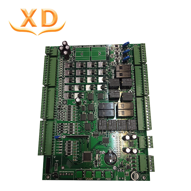
PCB mount 0402 components pcb assembly pcba with 8 smt line
Layer :4 Layer
Finish treatment: Immersion gold
Copper thickness: 1oz
Board thickness: 1.6mm
Green soldermask
Application: Airborne Recorders
PCB mount 0402 components pcb assembly pcba with 8 smt line
Then certain essential functions allow you to use these displays for residential and commercial advertisement activities,· High contrast and luminosity
· Broad angle of view
· Image playback and visuals, motion shown
· Rate the number of times an ad has been seen
· Online management and planning
· Daytime and range do not influence workload
The operating capability is not affected by the time of year, weather, and temperature change
The stability and long life of the LED show for up to 10 years is one of the biggest advantages. In addition, the show would not stop running, except though part of it is damaged. The defective cluster remains unnoticed.
PCB Product Capability:
PCB Manufacture Capacity | |
Item | Specification |
Material | FR-4, FR1,FR2; CEM-1, CEM-3,Rogers, Teflon,Arlon,Aluminum Base, Copper Base,Ceramic, Crockery, etc. |
Remarks | High Tg CCL is Available(Tg>=170℃) |
Finish Board Thickness | 0.2 mm-6.00mm(8mil-126mil) |
Surface Finish | Gold finger(>=0.13um), Immersion Gold(0.025-0075um), Plating Gold(0.025-3.0um), HASL(5-20um), OSP(0.2-0.5um) |
Shape | Routing,Punch,V-cut,Chamfer |
Surface Treatment | Solder Mask(black, green, white, red, blue, thickness>=12um, Block, BGA) |
Silkscreen(black, yellow, white) | |
Peel able-mask(red, blue, thickness>=300um) | |
Minimum Core | 0.075mm(3mil) |
Copper Thickness | 1/2 oz min; 12oz max |
Min Trace Width & Line Spacing | 0.075mm/0.075mm(3mil/3mil) |
Min Hole Diameter for CNC Drilling | 0.1mm(4mil) |
Min Hole Diameter for Punching | 0.6mm(35mil) |
Biggest panel size | 610mm * 508mm |
Hole Position | +/-0.075mm(3mil) CNC Drilling |
Conductor Width(W) | +/-0.05mm(2mil) or +/-20% of original |
Hole Diameter(H) | PTHL:+/-0.075mm(3mil) |
Non PTHL:+/-0.05mm(2mil) | |
Outline Tolerance | +/-0.1mm(4mil) CNC Routing |
Warp & Twist | 0.70% |
Insulation Resistance | 10Kohm-20Mohm |
Conductivity | <50ohm |
Test Voltage | 10-300V |
Panel Size | 110 x 100mm(min) |
660 x 600mm(max) | |
Layer-layer misregistration | 4 layers:0.15mm(6mil)max |
6 layers:0.25mm(10mil)max | |
Min spacing between hole edge to circuitry pattern of an inner layer | 0.25mm(10mil) |
Min spacing between board outline to circuitry pattern of an inner layer | 0.25mm(10mil) |
Board thickness tolerance | 4 layers:+/-0.13mm(5mil) |
What are the preparations before of PCB DIP soldering?
First Article Inspection
We will cross check and record all the supplied components’ quantity, item number, dimension, cathode direction, component silkscreen number, value, etc.
Components outline processing
Some components outline should be processed ahead of time because of their own design or for the PCB DIP soldering requirements and the whole PCB plan.
Requests. The horizontal witch of the processed pins should be the same as the locating holes, the tolerance should be < 5%, the silkscreen upward.
Components management
Preparation before DIP soldering: Every operator should follow team leader’s arrangement, prepare their WI content in their own station and receive all the components which match the WI completely. Put the received components into the part box and mark them well, including the defect parts if there is. Check if there is any cathode components, and compare with the WI picture, should be familiar with the part appearance and find out the pin position.
What is the process of DIP and SMT?
Dip soldering is accomplished by submerging parts to be joined into a molten solder bath. Thus, all components surfaces are coated with filler metal. Solders have low surface tension and high wetting capability. There are many types of solders, each used for different applications:
· Lead–silver is used for strength at higher-than-room temperature.
· Tin–lead is used as a general-purpose solder
· Tin–zinc is used for aluminium
· Cadmium–silver is used for strength at high temperatures
· Zinc–aluminium is used for aluminium and corrosion resistance
· Tin–silver and tin–bismuth are used for electronics.
Because of the toxicity of lead, lead-free solders are being developed and more widely used. The molten bath can be any suitable filler metal, but the selection is usually confined to the lower melting point elements. The most common dip soldering operations use zinc-aluminum and tin-lead solders.


